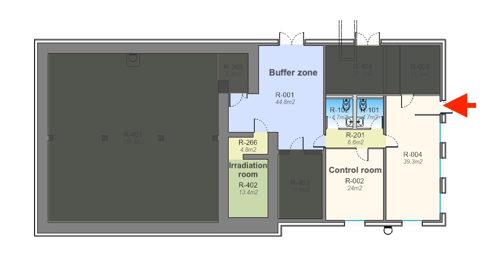
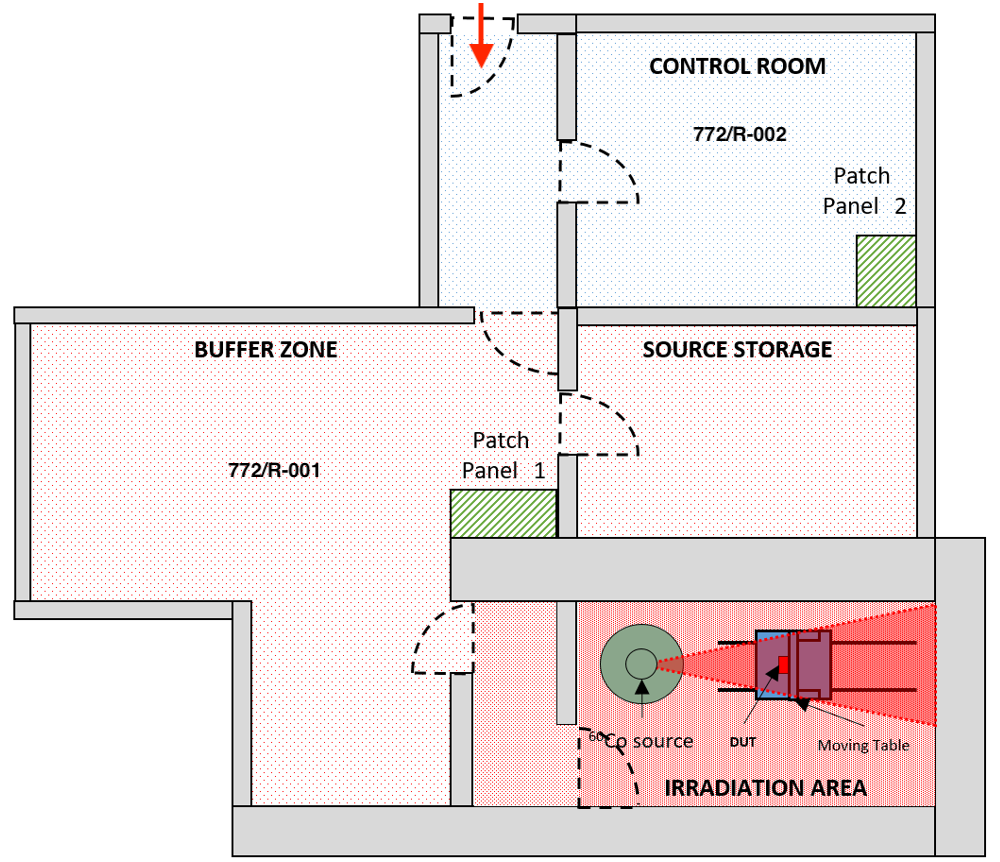
The layout of the CC60 facility is shown in the picture below. There are 3 main areas:
- Control room, where the irradiation is enabled/disabled. This is a non-radiological hazard area, no dosimeter is needed and can be accessed 24/7 once having obtained access rights. Here, a patch panel exists for recurring users performing optical fibres irradiations. If needed, few cables can be pulled from the irradiation room to the control room - to be arranged well in advance before the test -.
- Buffer zone: this is the access to the irradiation room, where material and equipment can be temporarily stored during tests, Power Supply and Data Acquisition systems can be set up and connected to the Devices Under Test. Cables can be easily pulled through feedthrough holes to the irradiation room. Total recommended cable length is 10-15 m, depending on the position inside the irradiation room. 220 V mains, ethernet, Wi-Fi are available, as well as two small tables for setups. A patch panel also exists with standard connections. Due to high-activity sources' special security regulations, this area cannot be freely accessed and the presence of CC60 personnel is needed to perform installation and dismounting. Consequently, if equipment installed here needs to be controlled during the test, Remote Connection should be set up.
- Irradiation room, where the Cobalt-60 source is installed and irradiation test take place. A movable table with an optical breadboard is available (100 mm grid of M6 threaded holes) to support small setups. Again, due to high-activity sources' special security regulations, this area cannot be freely accessed and the presence of CC60 personnel is needed to perform installation and dismounting.